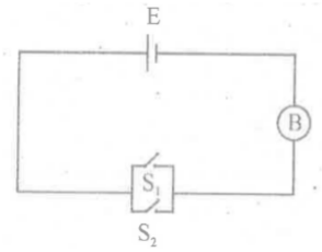
| A student made a circuit as shown in the figure. S1 and S2 are switches and B is a bulb. a) He argues that this circuit is equivalent to an AND gate. Do you agree with him? Justify your answer. b) Write down its truth table. |
 |
| Previous Year Questions of March Examinations from 2010 to 2020 |
| Chapter Name: SEMICONDUCTOR ELECTRONICS |
| A student made a circuit as shown in the figure. S1 and S2 are switches and B is a bulb. a) He argues that this circuit is equivalent to an AND gate. Do you agree with him? Justify your answer. b) Write down its truth table. |
 |
|
A photodiode is fabricated from a semiconductor of band gap energy 2.8 eV. a) Define band gap. b) Can this photodiode be used to detect a wavelength of 500 nm? Justify your answer. |
| Consider the logic circuit using NOR gates given in the figure a) Write the truth table for the circuit. b) Identify the logic operation which this circuit is performing. |
 |
| Match in 3 columns. |
 |
Given is the truth table of a 2-input logic gate.
A) Identify the logic gate B) Draw its logic symbol C) If this logic gate is connected to a NOT gate, what will be the output, when i) A=1, B=1 and ii) A=0, B=1? |
|
1) Choose the correct relation between the transistor parameters α and β . (A) β = (1- α ) / α (B) β = α / (1- α) (C) α β = (1 + α ) / α (D) β = α / (1 + α ) 2) Define the quantities α and β . 3) Give their possible range of values. |
| Biasing is provided for maintaining proper current flow across a p - n junction a) In a biased p - n junction the net flow of holes is from n region to p region b) For the device shown in below draw the V - I characteristics when the potential is applied between the terminals A and B c) A transistor can be used to amplify voltage or current. Explain how a transistor can be used as a current amplifier. Draw necessary circuit |
 |
|
We are familiar with the semiconductors, Silicon and Germanium a) With a necessary schematic diagram, briefly explains the charecteristics of an intrinsic semiconductor b) Draw the energy bands of a n-type semiconductor c) Draw a typical illuminated p-n junction solar cell d) LED converts ................ energy to light |
The truth table for a logic circuit is given below:
(b) Draw the logic symbol of the gate (c) Explain why NAND gate is known as universal gate? |
|
(A) Draw a circuit diagram of a transistor as an amplifier in common emitter configuration B) Obtain the expression for the voltage gain |
|
(A) What do you mean by barrier potential of a diode? (B) With the help of a diagram explain the working of a full wave rectifier |
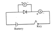
| (a) Which of the following are universal gates? i) AND gate ii) NAND gate iii) NOR gate iv) OR gate (b) Shown in figure is an experimental set up with a semiconductor diode (i) identify the experiment (ii) draw the resulting graph (c) with the help of a neat circuit diagram obtain an expression for voltage gain of a transistor amplifier in C-E configuration |
 |
| A zener diode is always operated in …………….. bias |
| Write down the truth table of a NOR gate |
| A message signal of frequency 10 KHz and peak voltage 10V is used to modulate a carrier of frequency 1 MHz and peak voltage 20V. Find the modulation index. |
| The current amplification factor for CB configuration of a transistor is 0.9. Find out the current amplification factor for CE configuration |
| Draw the symbol of NAND gate. |
| The symbol of a diode is shown in the figure: (a) The diode is a .................. (rectifier diode/ photo diode/ zener diode) (b) Draw the VI characteristics of above diode (c) A zener diode with Vz = 6.0 V is used for voltage regulation. The current through the load is to be 4.0 mA and that through the zener diode is 20 mA. If the unregulated input is 10.0 V, what is the value of series resistor R ? (d) What is the fundamental frequency of the ripple in a full wave rectiffer circuit operating from 50 Hz mains ? |
 |
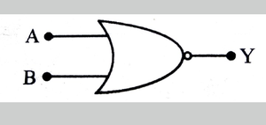
| Figure shows the symbolic representation of (i) OR gate (ii) NAND gate (iii) NOR gate (iv) NOT gate |
 |
|
The circuit used to change alternating voltage to direct voltage is called rectifier. (a) With a neat diagram, explain the working of a full wave rectifier having two diodes. (b) What is the output frequency of a full wave rectifier if the input frequency is 50 Hz? (e) Draw the output waveform across the load resistance connected in the full wave rectifier circuit. |
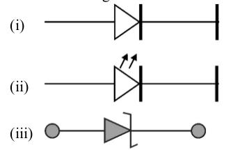
| Diodes are one of the building elements of electronic circuits. Some type of diodes are shown in the figure. a) Identify rectifier diode from the figure. b) Draw the circuit diagram of a forward biased rectifier diode by using a battery. |
 |
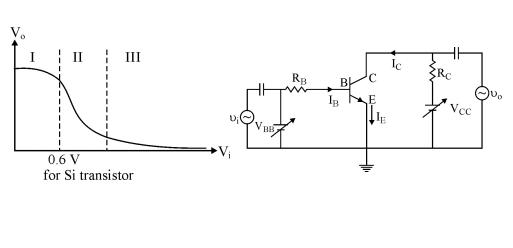
| The transfer characteristic of n-p-n transistor in CE configuration is shown in the figure (A) (a) Find the cut off region, active region and saturation region from it. (b) In which of these regions, a transistor is said to be switched off. (c) A CE transistor amplifier is shown in figure (B). In this, the audio signal voltage across collector resistance of 2.0 kΩ is 2.0 V. Suppose the current amplification factor of the transistor is 100. Then calculate the value of signal current through the base. (d) In the working of a transistor, the emitter-base (EB) junction is forward biased while collector base (CB) junction is reverse biased. Why ? |
 |